

2026 Top Multi Pair Instrumentation Cable Types for Buyers

In 2026, buyers need instrumentation cable that carries dependable signals through increasingly automated plants. The International Federation of Robotics reported 541,302 industrial robot installations worldwide in 2023, with 4.28 million robots in operation. These figures, published in World Robotics 2024, illustrate the scale of industrial automation. They do not forecast cable demand. That distinction matters.

A Multi Pair Instrumentation Cable can connect sensors, transmitters, and control equipment across a noisy factory floor. Selection depends on more than pair count: conductor size, insulation, shielding, capacitance, jacket material, and installation conditions all affect performance. Noise matters. A foil shield may suit some signal circuits, while braided shielding or an added drain wire may better match other grounding and flexing requirements. Buyers should also check the equipment specifications and relevant project standards, rather than treating cable types as interchangeable. Small details decide. This guide compares common constructions, including overall and individually shielded pairs, armoured options, and cables for demanding environments. It also considers practical trade-offs: a tougher jacket can add protection, but may increase cable stiffness and complicate routing. The right choice starts with the signal, surroundings, and installation—not a label alone.
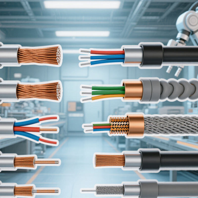
2026 Top Multi Pair Instrumentation Cable Types for Buyers

Multi-Pair Instrumentation Cable Basics: Pair Construction and 18 AWG Conductors

Multi-pair instrumentation cable groups insulated conductors into numbered pairs, often with each pair twisted to reduce magnetic interference. Pair colors and numbering make field identification faster, especially inside crowded panels. A shared overall shield or individual pair shields may be used, depending on noise exposure and grounding plans. Shielding is not magic.

An 18 AWG conductor offers a useful balance of size, strength, and termination space for many measurement circuits. Its resistance is higher than that of a larger conductor, so calculate voltage drop on long runs. Check device load, route length, ambient temperature, and the cable datasheet before specifying it. Tray congestion can complicate pulling, even when the schedule looks tidy.

Tips: Confirm pair count and shield construction against the instrument list, not just the cable label. Keep drain-wire bonding consistent with the project grounding design; bonding both ends is not always the right choice. Allow bend room. Label pairs before termination where practical.

Shielding Types: Individually Shielded Pairs, Overall Shields, and Both

For multi-pair instrumentation cable, shielding choice should follow the noise environment and signal sensitivity, not habit. Individually shielded pairs help limit pair-to-pair crosstalk, useful when low-level sensor signals share a route with switching or control circuits. An overall shield adds a shared barrier around the cable core, often practical where external electrical noise is the main concern. A shield is not magic.

Using both gives each pair local protection plus a common outer screen, but adds cost, diameter, and termination work. It can suit dense trays with mixed signal levels.

For context, IEC 61000-4-6:2023 covers conducted RF immunity testing from 150 kHz to 80 MHz; this range is a useful reminder that interference can travel along connected wiring.

IEC 62153-4-3:2013 specifies a triaxial method for measuring cable surface transfer impedance, a technical measure of screening performance. Neither reference means one construction fits every installation.

Check the cable data sheet for shield coverage, drain-wire details, and transfer-impedance results where available. At the panel, keep pair shields separated and terminate them as the equipment design specifies; grounding practice depends on the system and frequency.

A neat foil wrap can still perform poorly if a pigtail is long or routing is careless. I have seen that detail overlooked.

Specify the noise source, cable run, and termination plan before choosing individually shielded pairs, an overall shield, or both.

Cable Construction Options: Unarmored, Armored, and Fire-Resistant Designs

Multi-pair instrumentation cable carries several low-level signal circuits within one jacket, so its construction affects installation and reliability. Unarmored designs are lighter and easier to pull through trays or conduit with limited space. They suit protected indoor routes where impact and crushing risks are low. Still, a tough-looking jacket does not protect cable from every sharp edge. That matters.

Armored cable adds a metal layer, often interlocked or continuously applied, to resist mechanical damage. It can suit exposed runs, equipment skids, or areas with frequent maintenance traffic. The added weight may complicate bends, supports, and gland selection. Check bend-radius limits and termination details before ordering. I would not assume heavier always means safer; routing still matters.

Fire-resistant designs use materials and construction intended to maintain circuit integrity for a defined exposure period, depending on the tested specification. They may suit shutdown, alarm, or emergency communication circuits, but the label alone is not enough. Review test conditions, conductor size, shielding, and pair identification against project documents. A small mismatch can cause delays. Buyers sometimes focus on fire ratings and overlook tray fill or temperature limits. Confirm the complete cable schedule with the installer and engineer.

UL 2250 Voltage Classes: Comparing 300 V and 600 V Instrumentation Cables

UL 2250 instrumentation cables may be marked for 300 V or 600 V service. The rating describes the cable’s voltage class, not its signal accuracy. A 300 V cable can suit many control and measurement circuits when the equipment and installation requirements align. A 600 V option may be appropriate where the circuit voltage or specified design calls for it. Higher is not automatically better.

Check the cable marking and project specification before choosing. Confirm conductor size, insulation, shielding, temperature rating, and installation conditions too. For example, a cable routed beside power equipment may need careful shielding and separation, regardless of its voltage class. It is easy to focus too much on the number. That can leave other important details unchecked. The correct choice depends on the complete circuit and its environment.

Tips: Match the rating to the highest expected circuit voltage, then verify it against the equipment documentation. Keep a sample label or datasheet with the project records. If requirements are unclear, ask a qualified electrical professional before ordering. A small check now can prevent a costly replacement later.

Buyer Selection Factors: 4–20 mA Loops, EMI Exposure, and Installation Conditions

For 4–20 mA loops, check pair count, spare capacity, and loop resistance before choosing a cable. NAMUR NE 43 defines 3.8–20.5 mA as the usable measurement range. Fault signaling is at or below 3.6 mA, or at or above 21 mA. That margin matters when long runs, terminal blocks, and input cards add resistance. Verify transmitter compliance voltage and receiver burden before selecting conductor size. Small details count. Multi-pair cables simplify routing, while spare pairs can reduce later shutdown work. However, additional pairs increase cable diameter and may complicate tray bends.

Near variable-speed drives or contactors, specify twisted pairs and shielding appropriate to the noise environment. IEC 61000-4-6 covers conducted RF immunity from 150 kHz to 80 MHz, offering a useful reference for connected equipment testing. Shielding is not magic. Bonding, cable spacing, and grounding affect whether a screen helps or permits unwanted circulating currents. For outdoor or wet routes, review jacket material, UV exposure, oil contact, and temperature limits. IEC 60332-1-2 uses a 1 kW flame to test vertical flame spread on a single cable; it does not replace project-specific fire requirements. Check tray fill and minimum bend radius against the installation drawing. I would verify these details on site; drawings can miss crowded transitions.

2026 Top Multi Pair Instrumentation Cable Types for Buyers — Buyer Selection Factors: 4–20 mA Loops, EMI Exposure, and Installation Conditions

Cable Type Typical Construction 4–20 mA Loop Suitability EMI Considerations Installation Conditions Buyer Selection Checks
Unshielded twisted-pair multi-pair cable Insulated conductors are twisted into pairs; multiple pairs share an outer jacket without metallic screening. Can suit low-noise, short or well-controlled signal routes when permitted by the system design. Twisting helps reduce pickup from balanced interference, but the cable has no shield to limit external electromagnetic coupling. Best considered in electrically quiet areas, separated from power wiring and major noise sources. Check route proximity to variable-frequency drives, motors, transformers, and switching equipment; confirm project requirements allow unshielded cable.
Individually shielded pairs Each twisted pair has its own screen, commonly foil or braid; a drain wire may be provided for foil screens. A common choice where individual loop isolation from pair-to-pair coupling is important. Pair-level screens help reduce crosstalk and interference between neighboring circuits. They do not replace good routing or grounding practices. Useful in multi-loop runs and installations with several low-level signals in one cable route. Verify screen coverage, drain-wire details, pair identification, and the specified shield termination method.
Overall-shielded twisted-pair cable Twisted pairs are gathered under one shared metallic screen, typically foil or braid, and an outer jacket. Often suitable for groups of 4–20 mA loops when the shared-screen arrangement meets the project design. The overall screen provides a common barrier against external electric-field interference; it offers less pair-to-pair isolation than individual pair screens. Can be practical for compact installations with moderate interference and coordinated cable routing. Assess whether circuits can share a screen, and confirm screen continuity, bonding instructions, and the instrument system’s grounding scheme.
Individually and overall shielded pairs Each pair has its own screen, with an additional overall screen around the assembled cable core. Suitable for sensitive or densely grouped analog loops where both pair-to-pair and external interference control are required. Provides two levels of screening, but effectiveness still depends on correct termination, bonding, routing, and installation workmanship. Consider for electrically noisy areas or routes carrying multiple signal circuits, subject to the site’s cable and grounding standards. Check the construction and termination requirements for both screen levels; confirm the added diameter, stiffness, and cable-tray capacity.
Armored instrumentation cable Instrumentation pairs with a metallic armor layer, which may be combined with individual and/or overall screens. Loop performance depends mainly on the conductor, pair twist, and screening design; armor is not a substitute for signal shielding. Metallic armor can provide mechanical protection and may contribute to electromagnetic screening when designed and bonded accordingly. Consider for exposed routes or locations where impact, crushing, or other mechanical damage is a concern. Armor type must suit the environment. Specify armor material and coverage, required mechanical protection, cable gland compatibility, environmental exposure, and bonding requirements.
Fire-resistant or fire-survivable instrumentation cable Pairs and screens use materials or constructions selected to meet a defined fire-performance requirement; exact performance depends on the applicable test standard. May carry 4–20 mA circuits if the electrical, temperature, and installation ratings meet the system requirements. Screening performance varies by construction; fire performance alone does not establish EMI suitability. Used where project specifications require a stated level of circuit integrity or fire performance, with compatible supports and installation methods. Identify the required test standard and performance category; verify that the cable’s fire claim matches the project specification and local rules.
Low-capacitance twisted-pair instrumentation cable Pair geometry and insulation are selected to control conductor-to-conductor and conductor-to-screen capacitance; shielding may be included. Can be useful on longer runs or where loop response and total circuit capacitance are design concerns; allowable limits depend on the transmitter and input circuit. Low capacitance does not itself provide EMI protection; evaluate the shield and route separately. Relevant for long cable lengths, distributed systems, and circuits with defined capacitance limits. Compare the cable capacitance per unit length with the maximum permitted by the instrument, barrier, isolator, or control-system input.

Selection note: A 4–20 mA signal is generally less susceptible to voltage noise than a low-level voltage signal, but it is not immune to interference or installation errors. Confirm conductor size, loop resistance, cable capacitance, temperature and environmental ratings, hazardous-area requirements, screen termination, and separation from power circuits against the project specification and applicable codes. Follow the instrument and site grounding instructions; shield termination practices are system-dependent.

Choose a global leader for your hydraulics solutions

How can we help you?

Call to 0034 943884600 Contact us
Call us Contact us

We use cookies to ensure that we give you the best experience on our website. If you continue without changing your settings, we'll assume that you agree to receive cookies on the HINE website. For more information read our cookie policy page, click the link for more information.plugin cookies

ACEPTAR
Aviso de cookies