

How to Choose the Best Blade Antenna for UAVs in 2026?
In 2026, selecting a Blade Antenna For Uav means balancing signal performance with the realities of a compact airframe. A sleek profile alone does not guarantee dependable communication. Frequency range, polarization, radiation pattern, connector type, and installation space all affect the result. A few millimeters can matter. So can a carbon-fiber body, a nearby battery, or a cable routed too tightly around the fuselage.
This guide explains how to compare blade antennas against a UAV’s intended communication tasks and operating conditions. It examines gain and coverage, antenna placement, weight, environmental protection, and compatibility with the radio system. It also considers practical checks, such as reviewing manufacturer data, inspecting connector fit, and testing the installed antenna on the actual airframe. Bench results are useful, but flight configuration can change the picture. That part is easy to underestimate.
There is no single best antenna for every UAV. A lightweight mapping aircraft and a larger industrial platform may need different patterns, mounting arrangements, and durability. Buyers should confirm specifications with the manufacturer and assess performance using suitable test procedures. Even careful comparisons leave some uncertainty; airframes and installations vary. This article offers a clear framework for making a better-informed choice, while leaving room for measured testing rather than relying on product claims alone.
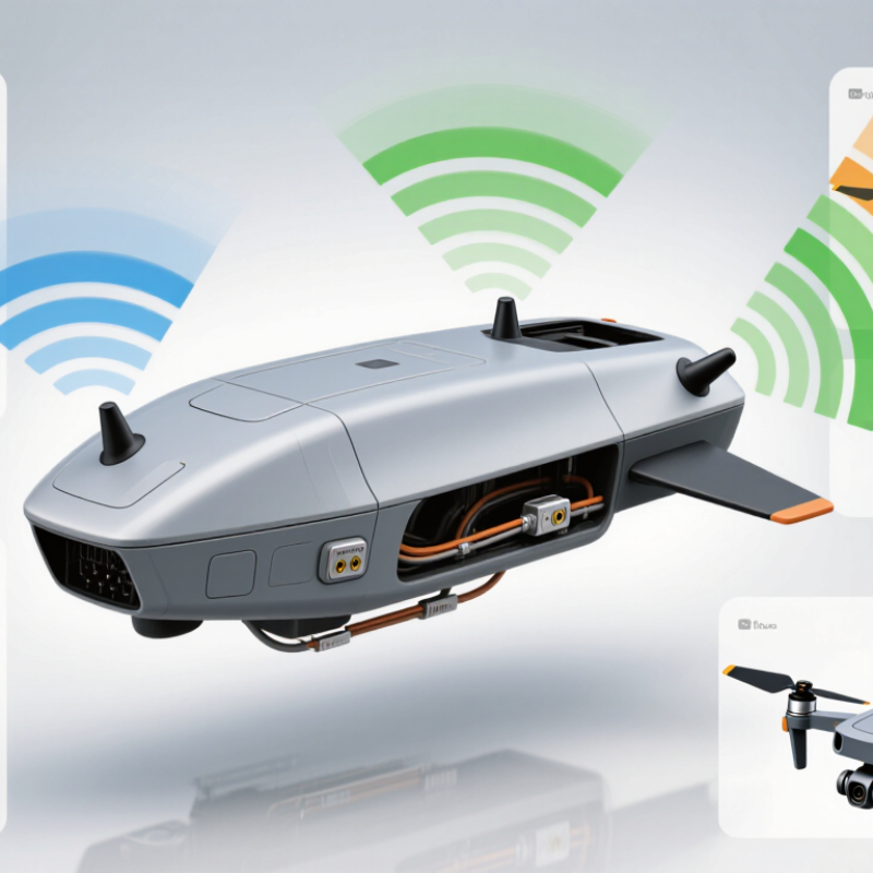
Understand Blade Antennas and UAV Communication Needs
A blade antenna is a low-profile radiator shaped to reduce drag and withstand airflow. Its compact form can suit UAVs, but shape alone does not determine performance. Frequency, polarization, and the aircraft’s conductive structure all affect the radiation pattern. Small details matter.
Start with the communication task. Control and telemetry may need a dependable link at modest data rates, while video can demand more bandwidth. These needs influence antenna frequency, placement, and the space available for the ground plane. A longer stated range is not automatically better if the link becomes unreliable as the aircraft turns. The first placement may look tidy, yet leave a weak heading.
Installation changes real-world results. A nearby battery, carbon-fiber panel, or metal fastener can alter tuning or block part of the signal. Keep the antenna clear of likely obstructions, secure its cable against vibration, and avoid sharp bends near the connector. Then test the mounted UAV in different orientations, not just on a bench. Bench results help, but they can flatter the setup. Check the intended operating frequency and confirm performance with appropriate equipment; estimates alone can miss losses from cables, connectors, and the airframe.
How to Choose the Best Blade Antenna for UAVs in 2026? — Understand Blade Antennas and UAV Communication Needs
| Selection dimension | UAV communication need | Blade antenna considerations | Practical selection check |
|---|---|---|---|
| Operating frequency | The antenna must match the assigned radio band; common UAV links use sub-GHz bands or frequencies around 1.2/1.3, 2.4, and 5.8 GHz, depending on region and application. | A blade is designed for a specified band or bands. A multiband design may involve trade-offs in size, efficiency, pattern, or bandwidth. | Confirm the radio’s exact transmit and receive frequencies, channel bandwidth, and local spectrum rules. Do not assume a nominally similar band is compatible. |
| Bandwidth and impedance match | The antenna should cover the full operating channel range and present a suitable impedance to the radio, commonly 50 ohms in RF systems. | Matching can shift when the antenna is installed on a different airframe or near conductive parts. A low VSWR across the required band is more useful than a single-point result. | Review measured return-loss or VSWR data over the intended band in the proposed installation. Check the radio’s permitted mismatch limits. |
| Link range and antenna gain | Range depends on the complete link budget, including transmit power, receiver sensitivity, cable loss, antenna patterns, interference, and line of sight. | Higher gain concentrates energy in some directions and can reduce coverage in others. A broad, near-omnidirectional pattern may be preferable when the UAV changes orientation. | Compare radiation patterns and gain across the relevant directions, not just peak gain. Verify that the planned link budget includes cable and connector losses. |
| Polarization | The aircraft antenna and ground-station antenna should use compatible polarization to limit polarization mismatch. | Blade antennas are commonly linearly polarized, though designs vary. Banking, yaw, and airframe attitude can change alignment with a ground antenna. | Check polarization and mounting orientation at both ends. Assess expected aircraft attitude and whether polarization diversity is needed. |
| Airframe integration | The installed antenna needs adequate clearance and a suitable RF reference environment to perform as intended. | Carbon-fiber structures and nearby batteries, wiring, motors, or metal parts can detune or obstruct an antenna. Blade shape alone does not guarantee a suitable radiation pattern. | Check the antenna’s specified ground-plane requirements and keep it clear of obstructions where possible. Test it on the assembled airframe, not only on a bench. |
| Mass, profile, and drag | The antenna and mounting hardware must fit the UAV’s payload, balance, and aerodynamic constraints. | Blade antennas can provide a low-profile alternative to some exposed whip antennas, but actual mass, height, and aerodynamic effects depend on the design and installation. | Compare documented dimensions and mass, then check clearance, fastener strength, center of gravity, and airflow for the airframe. |
| Environmental durability | Outdoor operation may expose the antenna to vibration, moisture, dust, temperature changes, and handling impacts. | Radome material, sealing, connector retention, and mounting design influence durability. Environmental ratings apply only under their stated test conditions. | Review operating-temperature and ingress-protection information where available. Inspect mounting and cable strain relief for the intended mission conditions. |
| Cable and connector | The feed line must connect securely to the radio while keeping RF loss and mechanical stress manageable. | Longer or thinner coaxial cable generally introduces more loss, with loss increasing with frequency. Connector type and cable routing also affect reliability. | Confirm connector compatibility, cable length, frequency-specific loss, bend limits, and strain relief before installation. |
| Compliance and verification | Radio operation must comply with the applicable regional frequency, power, and equipment requirements. | Antenna gain and installation can affect effective radiated power and system performance. Specifications should be validated in the final configuration. | Check local regulations and radio documentation. Verify the installed system with suitable RF measurements and a ground or flight test appropriate to the operation. |
Note: Frequency examples are common in UAV communication equipment but are not universally permitted or suitable. Confirm regional regulations and validate antenna performance in the final airframe installation.
Choose a global leader for your hydraulics solutions
How can we help you?
Call to 0034 943884600 Contact us