

A Car Battery Bus Bar is a compact conductor that links battery terminals, fuses, relays, and major electrical circuits. It usually consists of copper or aluminum, sometimes with tin plating for improved corrosion resistance. Instead of routing several thick cables from one battery point, the bus bar creates a shorter, cleaner distribution path.
Dr. Menahem Anderman, a respected battery-systems consultant, has emphasized a principle that fits this component well: “Safety must be designed into every layer of the battery system.” A bus bar supports that goal when engineers calculate current capacity, heat buildup, insulation, and connection strength together. A poorly sized bar can become hot under load. A loose terminal may create resistance, voltage loss, or visible discoloration around the joint.
The working process is straightforward. Battery current enters one conductive section, then travels across fixed connection points to different circuits. Bolted studs, threaded terminals, or integrated fuse links control where that energy goes. In a modern vehicle, the bus bar may sit inside a protected battery box, beneath a molded cover, near sensors and high-current contactors.
Small details matter.
Copper feels solid and heavy. A clean terminal stays cool. Engineers also inspect torque values, surface oxidation, vibration marks, and insulation clearance. These checks are often overlooked in simple explanations. Even so, a bus bar is not automatically safer than separate cables. Its performance depends on design, installation, and maintenance. That is the part worth questioning. A neat appearance does not prove electrical reliability.
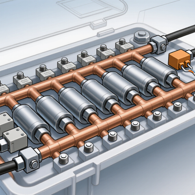
A car Battery Bus Bar is a solid electrical conductor near the battery. It connects one power source to several vehicle circuits. Most bus bars use copper, brass, or plated metal. An insulating cover often protects the exposed surface.
The battery sends current into the bus bar through a main terminal. From there, separate connection points feed the starter, fuse box, charging circuit, or accessory wiring. The bar provides a short, low-resistance path. It does not control current by itself. Fuses or circuit breakers protect the connected branches. This difference matters during diagnosis.
A bus bar should have firm terminals and clean contact surfaces. Even a small layer of corrosion can increase resistance. That may create heat, dim lights, or cause difficult starting. A technician can check for loose fasteners, damaged insulation, and unusual temperature after operation. Use a suitable meter for voltage-drop testing. Disconnect power before touching the assembly.
The simple design can be misleading. A bus bar is not automatically safe because it looks solid. An overloaded connection may still fail. Technicians should verify the rated current and cable size for each circuit. I have found that inspection results are not always perfect, especially when corrosion hides beneath a terminal. Careful retesting remains necessary.
A car battery bus bar is a solid conductive strip that joins several battery terminals. It creates one shared electrical connection instead of relying on many separate cables. Copper or tinned copper is often used because it carries high current with low resistance. The bar may include threaded posts, protective covers, or holes for ring terminals. Its size must match the vehicle’s expected current demand.
Multiple batteries can connect to the same bus bar in parallel. Positive terminals meet on one bar, while negative terminals connect to another. Current then flows from the batteries to the bar and into the starter, inverter, fuse panel, or other equipment. The bar spreads electrical load across a short, low-resistance path. It also keeps the battery compartment cleaner. Fewer loose cables usually mean easier inspection.
A secure installation matters. Each terminal should sit flat, stay free from corrosion, and receive the correct tightening force. Too little pressure can create heat. Too much can damage the terminal or stud. Add suitable overcurrent protection near the power source, especially on long cables. A cover helps prevent accidental contact with metal tools. During a workshop inspection, I have found that cable movement can loosen connections over time. I once underestimated that risk. Vibration deserves attention. Before testing, disconnect the power source and verify polarity with a meter, because one reversed connection can damage sensitive equipment.
A car battery bus bar is a solid conductor that distributes current between the battery, fuse links, starter, and vehicle circuits. Unlike a flexible cable, it uses a compact metal strip with fixed connection points. This layout reduces cable clutter and helps keep high-current paths short. In practical service work, clean contact surfaces matter as much as the bar itself.
Copper is common because it carries current efficiently and resists excessive voltage drop. Aluminum weighs less, but it needs careful joint design because oxidation can increase contact resistance. Many bus bars use tin or nickel plating. These coatings help limit corrosion and support more stable electrical contact.
The main body may include drilled terminals, threaded studs, washers, and locking nuts. Some designs also include plastic covers or molded insulation to prevent accidental contact.
Small details can cause trouble.
Loose fasteners create heat, while over-tightening can damage threads or distort the bar. A technician should check discoloration, melted insulation, white corrosion, and unusual battery voltage loss. A fuse link may protect one branch, but it cannot correct a poorly sized conductor. That point is easy to miss. Material choice, cross-sectional area, joint pressure, and environmental sealing must work together. The design may look simple, yet its reliability depends on careful installation and regular inspection.
A car battery bus bar is a conductive metal strip that joins several electrical paths. It distributes current between the battery, starter, fuse box, and vehicle ground. Unlike a thin wire, it offers a short, low-resistance route. This matters when the starter demands hundreds of amperes for a few seconds.
Electrical current leaves the battery’s positive terminal and enters the bus bar. It then divides according to each circuit’s resistance and protection rating. The starter receives the largest immediate flow. Smaller branches supply lighting, control modules, and charging circuits. Current returns through the chassis or a dedicated ground cable. According to SAE J537 testing guidance, automotive batteries are commonly evaluated around a 12-volt system, although charging voltage rises above that level during operation.
The bus bar must carry high current without excessive heating. The U.S. Department of Energy identifies the low-voltage battery as essential for starting and supporting vehicle electrical loads. Battery Council International reports that lead batteries achieve more than 99% collection and recycling in the United States. That statistic supports the durability and established service life of this system, but it does not remove inspection needs. Loose fasteners create resistance. Resistance creates heat. Heat can discolor metal, soften insulation, and reduce starting performance.
A practical check is simple. Look for white corrosion, darkened terminals, or melted plastic near the connection. Voltage loss should be measured under load, not only with the engine off. The ideal current path is clean, tight, and short. Real vehicles are less perfect. Even a strong battery cannot overcome a poor bus-bar connection.
| Data Dimension | Typical Information | How It Relates to Current Flow | Practical Consideration |
|---|---|---|---|
| Basic Definition | A solid electrical conductor that distributes power from a battery terminal to multiple circuits or connection points. | Current enters the bus bar through one high-current connection and divides into several outgoing paths. | It replaces multiple joined cables with a compact, organized, and lower-resistance distribution point. |
| Typical Vehicle Voltage | Approximately 12 V in conventional passenger vehicles; approximately 24 V in many heavy-duty vehicles. | Voltage provides the electrical potential that drives current through connected loads. | The bus bar must be rated for the system voltage and any transient voltage that may occur. |
| Common Conductor Material | Copper is common because its electrical conductivity is about 58 MS/m at 20°C. Aluminum is lighter but has lower conductivity, about 35 MS/m at 20°C. | Higher conductivity reduces resistance and limits power loss for a given current. | Material choice affects weight, required cross-sectional area, corrosion protection, and terminal design. |
| Typical Shape | A flat metal strip or bar with drilled holes, threaded studs, or integrated terminal points. | The broad conductor provides a shared low-resistance path between the battery and several branches. | Rounded edges, protective covers, and sufficient spacing help prevent accidental shorts. |
| Main Current Path | Battery positive terminal → main cable → bus bar → branch fuse or circuit → electrical load → chassis ground or negative return. | The bus bar carries the combined current of active downstream circuits before it separates into individual branches. | The negative side may use a separate negative bus bar or the vehicle chassis as the return path. |
| Current Division | For parallel branches, the total current is approximately the sum of branch currents: ITotal = I1 + I2 + I3 + … | A 30 A load and a 10 A load operating together require approximately 40 A from the shared upstream section. | The main bus bar and its feed cable must be sized for the maximum simultaneous load, not only one branch. |
| Typical Current Range | Small auxiliary distribution bars may handle tens of amperes; starter and main battery distribution bars may handle several hundred amperes for short periods. | The required rating depends on continuous current, peak current, duty cycle, ambient temperature, and allowable temperature rise. | A bus bar must not be selected solely by physical size; its complete assembly rating is important. |
| Electrical Resistance | Conductor resistance follows R = ρL/A, where ρ is resistivity, L is length, and A is cross-sectional area. | A shorter, wider, and more conductive bus bar generally has lower resistance. | Resistance increases with poor connections, corrosion, loose fasteners, and excessive conductor temperature. |
| Voltage Drop | Voltage drop is calculated as VDrop = I × R. Power loss is P = I² × R. | High current magnifies the effect of even small resistance, especially at the battery connection and terminal joints. | Low-resistance joints help maintain stable voltage and reduce unwanted heat. |
| Protection Method | Fuses or fusible links are normally installed close to the battery or at the bus-bar branches. | Protection interrupts excessive current before a cable, bus bar, or connected device overheats. | A fuse rating should protect the wiring and circuit, not simply match the maximum possible load. |
| Connection Hardware | Common hardware includes threaded studs, nuts, washers, cable lugs, crimped terminals, and protective covers. | Each joint adds a small amount of contact resistance to the overall current path. | Correct torque, clean contact surfaces, and strain relief are essential for reliable high-current operation. |
| Thermal Behavior | Heat generation increases according to P = I²R; doubling current produces approximately four times the resistive heating if resistance remains constant. | Continuous high current can raise the temperature of the bar, terminals, and surrounding insulation. | Allow ventilation and derate the assembly when installed in a hot engine compartment or enclosed space. |
| Safety and Maintenance | Inspect for discoloration, melted insulation, corrosion, loose fasteners, damaged covers, and abnormal heating. | A degraded connection increases resistance, causing voltage drop and localized heat while current continues to flow. | Disconnect the battery before servicing the bus bar and prevent tools from bridging positive and negative conductors. |
What Is a Car Battery Bus Bar and How Does It Work?
A car battery bus bar is a solid metal conductor that distributes current between battery terminals, fuses, relays, or cell groups. It replaces several loose cables with one compact connection point. In a 12-volt vehicle, it may link the battery to the starter and power distribution system. In electric vehicles, bus bars connect battery modules and carry high current through the pack. The IEA Global EV Outlook 2024 reported nearly 14 million electric car sales in 2023. That growth increases the importance of reliable internal connections.
Safety depends on spacing, insulation, torque, and corrosion control. A loose fastener can create resistance, heat, and an irritating burnt-plastic smell. Disconnect the negative terminal before inspection, then check for discoloration, cracked insulation, or white corrosion. Use an insulated tool. Never guess the tightening torque; follow the vehicle service specification. SAE J537 provides performance requirements for automotive storage batteries, but it does not replace model-specific repair instructions.
Keep it dry.
Maintenance is simple but not careless. Measure voltage drop across the connection under load, rather than relying only on visual checks. Clean oxidation with an approved method and replace damaged hardware. Bus bars appear in starter systems, auxiliary battery banks, fuse panels, hybrid packs, and EV battery modules. However, high-voltage packs require trained technicians and proper isolation equipment. I have seen “clean” connections fail after vibration testing, which is a useful reminder: appearance alone proves very little.
A bus bar is a solid copper or aluminum conductor that distributes battery power to multiple circuits with lower resistance and fewer cable connections. The chart shows common nominal electrical-system voltages where battery bus bars are used.
Safety and maintenance: Always disconnect the battery before servicing a bus bar. Use suitable insulation, correct overcurrent protection, secure fasteners, and manufacturer-specified torque. Inspect periodically for looseness, discoloration, corrosion, heat damage, or damaged insulation.
How can we help you?
Call to 0034 943884600 Contact usWe use cookies to ensure that we give you the best experience on our website. If you continue without changing your settings, we'll assume that you agree to receive cookies on the HINE website. For more information read our cookie policy page, click the link for more information.plugin cookies
ACEPTAR