

A Flanged Type Globe Valve is a pressure-control device designed for accurate flow regulation in industrial piping systems. Its flanged ends connect to matching pipe flanges with bolts, gaskets, and controlled tightening. Inside the body, a stem moves a disc vertically toward or away from a stationary seat. This movement changes the flow area and allows operators to adjust, start, or stop fluid service.
The design is easy to visualize. Picture a metal disc lowering onto a circular seat. A handwheel, actuator, or pneumatic system controls that movement. Unlike a gate valve, a globe valve guides fluid through a changing direction inside the body. This creates useful throttling control, but it also produces greater pressure loss. That trade-off matters in steam, cooling water, fuel, and chemical process lines.
Industry references support this practical distinction. API 623 provides requirements for steel globe valves used in petroleum and natural gas applications. ASME B16.34 addresses valve pressure-temperature ratings, materials, and testing considerations. ASME B16.5 covers many flange dimensions and pressure classes. These standards do not replace engineering judgment. They frame it.
Market research also shows why this valve remains relevant. Grand View Research’s industrial valves market analysis links demand to water infrastructure, energy projects, chemical processing, and manufacturing investment. MarketsandMarkets reports similar growth drivers across process industries. Exact forecasts vary by methodology. That uncertainty deserves attention.
In service, seat condition, packing compression, corrosion, and actuator sizing affect performance. Small installation errors can become expensive leaks. The explanation here is practical, not flawless. Always verify the medium, temperature, pressure, trim, and applicable local standards before selection.
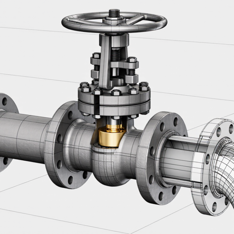
A flanged type globe valve is an industrial valve designed to control or stop fluid flow. Its body uses flanges, bolted connections, and a gasket to join adjoining pipe sections. This arrangement creates a firm, serviceable connection for water, steam, air, oil, and compatible process fluids. The core purpose is controlled flow, not merely open-or-closed isolation. It matters.
Inside the body, a movable disc travels toward or away from a stationary seat. A handwheel, actuator, or stem mechanism moves the disc along a mostly straight path. When the disc approaches the seat, the passage narrows and flow decreases. When it lifts, fluid passes through the valve chamber. The changing opening lets operators adjust pressure, temperature, or downstream volume with practical precision. However, internal direction changes can create more pressure loss than other valve designs.
In field service, technicians check flange alignment, gasket condition, bolt tightening, and stem movement. A small misalignment may cause leakage after thermal cycling. Correct sizing also matters. An oversized valve may control poorly at low flow. An undersized valve can restrict capacity and increase operating stress. Globe valves are reliable when their materials, pressure rating, trim, and temperature limits match the service. They are not perfect for every pipeline. That limitation deserves honest attention during selection.
A flanged type globe valve controls fluid flow through a movable disc and fixed seat. Its flanged ends connect to matching pipeline flanges with bolts and a gasket. The valve body guides the fluid through an internal passage. A bonnet covers the upper section and supports the stem. Inside, the disc moves toward the seat as the handwheel turns. This movement narrows the passage and regulates flow. It is not merely an on-off device.
The stem transfers handwheel movement to the disc. Threaded stems provide precise adjustment, while packing around the stem helps prevent leakage. The seat creates the sealing surface, but its condition strongly affects performance. A damaged gasket may leak even when the internal disc works correctly. In field inspections, uneven bolt tightening is often overlooked. It can distort the gasket and weaken the connection. The valve usually creates more pressure loss than a straight-through valve because fluid changes direction inside the body.
Tips: Check the flow arrow before installation. Tighten flange bolts gradually in a cross pattern. Keep the stem clean and lightly lubricated when suitable. During operation, turn the handwheel slowly to avoid water hammer. Do not force a stuck valve; corrosion, excessive pressure, or a damaged seat may be responsible. A visual inspection helps, but it cannot replace pressure testing. Even experienced technicians can miss small packing leaks during a busy shutdown.
A flanged globe valve uses bolted pipe connections and an internal disc to regulate fluid movement. Its body contains a curved passage, a seat, and a movable plug-like disc. The stem connects the disc to a handwheel or actuator above the bonnet. During installation, technicians place a gasket between the valve flanges, then tighten the bolts evenly. This creates a sealed joint and keeps the valve aligned with the pipeline.
When the handwheel turns, the stem moves the disc vertically. Turning it counterclockwise usually lifts the disc from the seat. Fluid then enters, passes around the disc, and leaves through the outlet. Turning the wheel clockwise lowers the disc toward the seat. The opening becomes smaller, so flow slows gradually. With the disc fully seated, the valve stops most flow. It is not simply an on-off device. Its internal shape supports careful throttling, although pressure loss can be noticeable.
Tips: Check the flow arrow before installation. Confirm the pressure, temperature, and fluid compatibility. Tighten flange bolts in a cross pattern. Operate the valve slowly to reduce water hammer. Inspect the stem and packing for leakage. A partly open valve may vibrate under unstable conditions. That detail is easy to miss. In practice, control quality depends on disc position, system pressure, and operator judgment. The valve may perform differently from a textbook example. Allow room for maintenance around the handwheel and bonnet.
A flanged globe valve connects to piping through two bolted flange faces. This design allows easier removal during maintenance. Common connections include raised-face, flat-face, and ring-type joint flanges. The selected connection must match the pipe flange, gasket, pressure class, and temperature range. Compatibility matters.
Raised-face flanges are widely used in industrial piping. They usually require spiral-wound or suitable compressed gaskets. Flat-face flanges need full-face gaskets and even bolt loading. Ring-type joints provide strong sealing for demanding service, but their grooves and metal rings require careful inspection. These connections are not interchangeable without proper engineering review.
Before installation, confirm the valve size, pressure rating, body material, and flow arrow. Clean both flange faces. Remove rust, paint, and old gasket fragments. Keep the valve supported; oversized valves can strain nearby pipework. Insert the gasket centrally, then tighten bolts gradually in a diagonal pattern. Use a calibrated torque wrench and follow the approved torque sequence. Hand-tightening is not enough.
I have seen leaks caused by a gasket shifted only a few millimeters. Small errors matter. Pipe misalignment should never be corrected by forcing the valve between flanges. That practice can distort the body or damage sealing surfaces. After assembly, inspect bolt projection and check for movement during pressure testing. Thermal expansion still deserves attention, even when the initial test shows no leakage.
What Is a Flanged Type Globe Valve and How Does It Work?
A flanged type globe valve controls flow with a movable disc and matching seat. Turning the handwheel moves the stem, raising or lowering the disc. The disc travels across the flow path, allowing precise adjustment. Flanged ends connect to pipes with bolts, gaskets, and aligned faces. This design supports strong, stable installation in industrial piping systems.
Typical Applications, Benefits, and Limitations
Globe valves often serve steam, cooling water, hot oil, and process fluid lines. They perform well where operators need frequent throttling or reliable isolation. Their changing flow path gives better control than many simple gate valves. They also provide predictable operation during gradual opening. However, pressure loss can be significant. The internal path is not straight. Continuous throttling may cause seat wear, vibration, or erosion, especially with dirty fluids. These valves can also require more operating force and space than compact alternatives. In practice, no valve choice is perfect. A model that works well on clean steam may struggle with abrasive slurry.
Tips: Check the pressure, temperature, fluid cleanliness, and required flow range before selection. Confirm flange ratings and gasket compatibility. Install the valve according to the flow arrow, if specified. Keep the stem accessible for inspection. A slightly oversized valve may throttle poorly, so “bigger” is not always safer. Regularly inspect packing, bolts, and leakage points. Small leaks often become expensive problems.
| Data Dimension | Key Information | Technical Details | Practical Considerations |
|---|---|---|---|
| Definition | A flanged globe valve is a linear-motion valve with flanged end connections, designed to start, stop, or regulate fluid flow. | Its closing element moves vertically toward or away from a stationary seat. The flanges are bolted to mating pipe flanges with a gasket between them. | It is commonly selected where reliable isolation and accurate throttling are required. |
| Main Components | Body, bonnet, stem, handwheel or actuator, disc or plug, seat, packing, and gasket. | The body contains the flow passage; the bonnet supports the stem; packing limits leakage around the moving stem; the seat provides the sealing surface. | Material selection depends on fluid chemistry, temperature, pressure, erosion risk, and applicable piping standards. |
| Working Principle | Turning the handwheel or operating the actuator moves the stem and disc along the valve axis. | When the disc approaches the seat, the flow area decreases. When it lifts away, the flow area increases. Flow direction is typically arranged beneath the disc for many services, but the manufacturer’s flow-direction marking should be followed. | The valve should be operated gradually to reduce the risk of pressure surges and excessive seat wear. |
| Flow Control Capability | Globe valves generally provide better throttling control than gate valves. | The changing opening between the disc and seat allows the flow rate to be adjusted over a useful operating range. | For precise automatic control, a properly sized control valve with a suitable trim and actuator may be more appropriate. |
| Typical Applications | Steam, hot water, cooling water, compressed air, process fluids, and utility services. | Common installation points include boiler feed systems, steam lines, water-treatment systems, heating circuits, chemical-process piping, and general industrial utilities. | The valve must be compatible with the fluid, pressure class, temperature range, pipe size, and required flow coefficient. |
| Flanged Connection | The valve is connected to the pipeline using bolted flanges and a gasket. | Flanged connections simplify removal for inspection or maintenance and are available in standardized pressure and dimensional ratings. | Correct flange alignment, gasket selection, bolt tightening, and torque sequence are essential to prevent leakage and mechanical stress. |
| Pressure and Temperature Rating | Performance is determined by the valve design, material, pressure class, temperature, and applicable standard. | A valve rated for a specific pressure at ambient temperature may have a lower allowable pressure at elevated temperature. The pressure-temperature table must be checked before selection. | Never select a valve based only on nominal pipe size; verify the complete rating and service conditions. |
| Key Benefits | Good throttling performance, dependable shutoff, robust construction, and straightforward maintenance access. | The linear stem movement provides predictable operation, while the replaceable or serviceable seat and packing can support maintenance programs. | Suitable for systems where flow regulation is more important than achieving the lowest possible pressure loss. |
| Main Limitations | Higher pressure loss, larger installation footprint, and greater operating effort than some other valve types. | The internal flow path changes direction, creating more resistance than a fully open gate or ball valve. Continuous throttling can also cause erosion, noise, or cavitation if the valve is incorrectly sized. | It is generally not the first choice for applications requiring very low pressure drop or frequent rapid on-off cycling. |
| Orientation and Installation | Many globe valves can be installed in horizontal or vertical pipelines, subject to design and service requirements. | The stem should have adequate clearance for operation and maintenance. The valve body arrow, installation instructions, and drainage requirements should be observed. | Pipe supports should prevent the valve from carrying excessive external loads caused by misalignment or thermal expansion. |
| Maintenance Requirements | Routine checks typically include external leakage inspection, stem and packing inspection, bolt condition, and operating performance. | Internal maintenance may involve cleaning, seat inspection, disc inspection, packing replacement, and gasket replacement after disassembly. | Before maintenance, isolate, depressurize, drain, and verify the system is safe according to the site’s procedures. |
| Selection Checklist | Consider nominal size, pressure class, temperature, fluid composition, flow rate, shutoff requirement, and actuation method. | Confirm body and trim materials, flange dimensions, gasket compatibility, end-to-end dimensions, flow direction, and applicable design or testing standards. | Proper sizing helps prevent excessive pressure loss, unstable control, vibration, premature wear, and inadequate capacity. |
How can we help you?
Call to 0034 943884600 Contact usWe use cookies to ensure that we give you the best experience on our website. If you continue without changing your settings, we'll assume that you agree to receive cookies on the HINE website. For more information read our cookie policy page, click the link for more information.plugin cookies
ACEPTAR