

How to Choose a Pressure Relief Valve in 2026?
Choosing a Pressure Relief Valve in 2026 requires more than comparing price, size, and connection type. The valve must match the actual hazard, not an idealized datasheet. Fluid phase, relieving temperature, set pressure, backpressure, corrosion, and discharge routing all matter. A valve that looks correct on paper may chatter, leak, or fail to protect equipment under unstable operating conditions.
Industry forecasts show continued demand. Grand View Research estimates the global pressure relief valve market will expand through 2030, driven by stricter process safety requirements, expanding energy infrastructure, and chemical production. However, market reports use different definitions and estimates. Their numbers should guide planning, not replace engineering verification. API 520, API 521, and ASME Boiler and Pressure Vessel Code Section VIII remain essential references for sizing, installation, and inspection.
Process-safety expert Trevor Kletz offered a warning that remains highly relevant: “If you think safety is expensive, try an accident.” His statement captures the real cost of weak relief protection. Yet selection is not always obvious. A spring-loaded valve may suit a conventional vessel, while a pilot-operated design may perform better with high flow demand or variable pressure. Sometimes, the cheapest option is the least economical choice.
This guide examines how to choose a Pressure Relief Valve in 2026. It focuses on credible data, operating evidence, and practical engineering judgment. Some decisions will remain uncomfortable. That is normal. A neat answer can still be wrong.
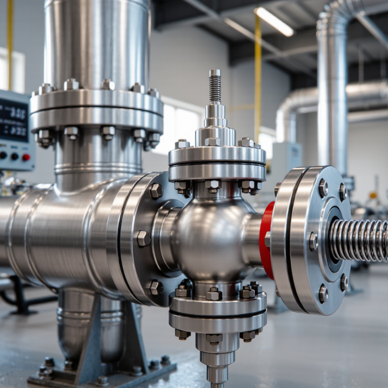
Pressure Relief Valve Basics: Purpose, Types, and Key Terminology
How to Choose a Pressure Relief Valve in 2026?
A pressure relief valve protects equipment when internal pressure rises beyond a safe limit. It opens, releases excess pressure, and helps prevent vessel damage. The set pressure is the point where the valve begins to lift. Blowdown describes the pressure drop required before it closes again. These terms matter during real operation, not only on technical drawings. A valve sized by pipe diameter alone may still perform poorly.
Common designs include spring-loaded, pilot-operated, and vacuum relief valves. Spring-loaded valves suit many straightforward systems and are usually easier to inspect. Pilot-operated valves can provide accurate control in larger or more demanding installations. Vacuum relief valves protect tanks from collapsing during draining or cooling. Check the required flow capacity, fluid temperature, corrosion risk, and discharge direction. Backpressure also matters. It can reduce capacity or change the opening behavior. I have seen selection errors begin with incomplete operating data. That detail is easy to underestimate.
Tips: Record normal pressure, maximum allowable pressure, temperature, fluid state, and expected flow before choosing. Confirm certified sizing calculations and applicable safety requirements with a qualified engineer. Leave room for maintenance access. A practical field check can reveal blocked discharge piping, dirt around the seat, or an incorrectly installed gauge. Do not rely on old settings without verification. Conditions change, and assumptions age.
How to Choose a Pressure Relief Valve in 2026? - Pressure Relief Valve Basics: Purpose, Types, and Key Terminology
| Category | Term or Valve Type | Meaning or Operating Principle | Selection Considerations | Typical Use or Technical Note |
|---|---|---|---|---|
| Purpose | Pressure relief valve | An automatic device that opens when system pressure reaches a defined value and discharges fluid to prevent pressure from exceeding a safe limit. | Confirm the protected equipment’s allowable pressure, required relieving capacity, fluid properties, and discharge destination. | Used on pressure vessels, boilers, piping systems, compressors, pumps, and thermal expansion sections. |
| Valve Type | Safety valve | A pressure relief valve designed to open rapidly, typically with a pop action, when the set pressure is reached. | Choose when rapid pressure reduction is required, especially for compressible fluids such as steam or gas. | Commonly applied to steam and gas service; discharge may be accompanied by an audible release. |
| Valve Type | Relief valve | A pressure-operated valve that normally opens progressively in proportion to increasing pressure. | Often selected for liquid service, where controlled discharge and stable reseating are important. | Liquid relief valves are commonly installed on pumps, hydraulic systems, and liquid-filled equipment. |
| Valve Type | Safety relief valve | A general term for a valve capable of relieving pressure using either pop action or proportional opening, depending on design and service. | Useful when the service may involve either liquids or compressible fluids, but the exact certified design must be verified. | The terminology can vary by industry and jurisdiction, so the applicable code and certification should be checked. |
| Valve Type | Direct spring-loaded valve | A spring directly opposes the process pressure acting beneath the disc. | Select for simple, independent operation and moderate pressure ranges; check spring temperature limits and backpressure sensitivity. | Widely used because of its relatively simple construction, easy maintenance, and reliable fail-open behavior. |
| Valve Type | Pilot-operated pressure relief valve | A pilot control uses system pressure to control the opening of the main valve. | Consider for high flow capacity, high operating-to-set-pressure ratios, or applications requiring reduced simmer. | Requires clean, compatible pilot-system fluid and careful evaluation of sensing lines, freezing, fouling, and loss of pilot pressure. |
| Valve Type | Balanced-bellows valve | A bellows arrangement reduces the effect of variable or built-up backpressure on the spring and set-pressure behavior. | Choose when discharge backpressure is significant or variable and conventional spring loading may be affected. | The bellows must be compatible with the process and protected from corrosion, plugging, or mechanical damage. |
| Valve Type | Vacuum relief valve | Opens when external pressure exceeds internal pressure by the specified vacuum setting, preventing excessive vessel vacuum. | Use when tanks or vessels may experience vacuum during draining, cooling, condensation, or blocked-in conditions. | A pressure-only relief valve may not provide vacuum protection; positive-pressure and vacuum duties may require separate devices. |
| Core Terminology | Set pressure | The inlet pressure at which the valve is adjusted to begin the specified opening action under defined test conditions. | Set pressure must not exceed the allowable pressure of the protected equipment, subject to the governing code. | It is normally stated in bar, kPa, MPa, psi, or another approved pressure unit. |
| Core Terminology | MAWP | Maximum allowable working pressure: the highest pressure permitted at a specified temperature for the protected equipment. | Use the lowest applicable MAWP among the protected components when establishing the protection basis. | MAWP is equipment-specific and is not interchangeable with normal operating pressure. |
| Core Terminology | Overpressure | The pressure increase above set pressure during the valve’s relieving operation, usually expressed as a percentage. | The allowable value depends on the applicable design code, service, and certified valve capacity. | Do not assume a universal percentage; confirm the required code limits for the installation. |
| Core Terminology | Accumulation | The pressure increase above MAWP while a relieving device is discharging during an overpressure event. | Evaluate together with the design code and the specific credible overpressure scenario. | Accumulation and overpressure may have different reference pressures, so they should not be treated as identical terms. |
| Core Terminology | Blowdown | The difference between the set pressure and the pressure at which the valve reseats, commonly expressed as a percentage of set pressure. | A smaller blowdown can reduce product loss but may increase the risk of unstable operation if the system is poorly designed. | The actual blowdown depends on valve design, service conditions, and adjustment. |
| Sizing Data | Required relieving capacity | The mass or volume flow rate that must be discharged to prevent pressure from exceeding the permitted limit during a defined scenario. | Calculate the governing scenario, such as blocked outlet, fire exposure, tube rupture, thermal expansion, or control-valve failure. | Typical units include kg/h, kg/s, Nm³/h, Sm³/h, L/min, or gal/min. |
| Sizing Data | Relieving pressure and temperature | The pressure and temperature at the valve inlet during the relief event, including applicable overpressure. | Use these conditions—not only normal operating conditions—for capacity calculations and material selection. | Gas, vapor, steam, liquid, and two-phase flow may require different sizing methods. |
| Installation | Backpressure | Pressure at the valve outlet caused by discharge-system pressure, including superimposed and built-up components. | Determine whether the backpressure is constant or variable and select a suitable valve design or discharge arrangement. | Excessive backpressure can reduce capacity, alter set-pressure behavior, or cause instability in some spring-loaded valves. |
| Installation | Inlet pressure loss | The pressure drop between the protected equipment and the relief-valve inlet during discharge. | Keep inlet piping short and properly sized; excessive loss can cause unstable opening and closing. | Evaluate fittings, reducers, isolation valves, and the full inlet flow path. |
| Materials | Fluid compatibility | The compatibility of wetted materials, seals, and internal components with the process medium. | Check corrosion, erosion, toxicity, flammability, viscosity, solids content, and temperature effects. | Material selection must consider both normal conditions and the most severe credible relieving condition. |
| Compliance | Applicable design code | The legal, regulatory, or engineering standard governing valve design, sizing, testing, installation, and inspection. | Identify the jurisdiction and equipment category before selecting a certified valve or sizing method. | Common references include pressure-vessel, boiler, piping, and relief-device standards; requirements vary by location and service. |
| Final Selection Checklist | Minimum specification data | A complete selection normally requires valve function, fluid phase, composition, normal and relieving conditions, set pressure, capacity, backpressure, materials, connection size, and discharge arrangement. | Do not select by nominal pipe size or set pressure alone; verify certified capacity and installation limitations. | Final sizing and code compliance should be reviewed by a qualified pressure-systems engineer. |
Choose a global leader for your hydraulics solutions
How can we help you?
Call to 0034 943884600 Contact us