

A Valve Seal is a small component with a critical responsibility: preventing fluid or gas from escaping around a valve stem, bonnet, or internal moving part. In a processing plant, one worn seal can leave a thin wet mark, create pressure loss, or cause an unnoticed emission. Its importance often becomes visible only after failure.
Valve seals are not a single, universal design. Common types include O-ring seals, lip seals, packing seals, diaphragm seals, and bellows seals. Each type suits different pressures, temperatures, chemicals, and movement patterns. Material choices may include elastomers, graphite, PTFE, or engineered polymers. Selection requires more than matching dimensions. Compatibility matters.
Small details matter.
For example, a seal designed for water may perform poorly with hot oil or aggressive chemicals. Installation quality also affects service life. A twisted O-ring, uneven compression, or contaminated sealing surface can cause premature leakage. These problems are easy to underestimate, even in professional maintenance work. No seal is perfect, and every design involves trade-offs between flexibility, durability, friction, and cost.
This guide explains what a Valve Seal does, how its main types differ, and where each design is commonly used. It also considers operating conditions, material behavior, inspection practices, and practical failure signs. The information reflects established engineering principles, but manufacturers’ specifications should always guide final selection. That step is sometimes overlooked.
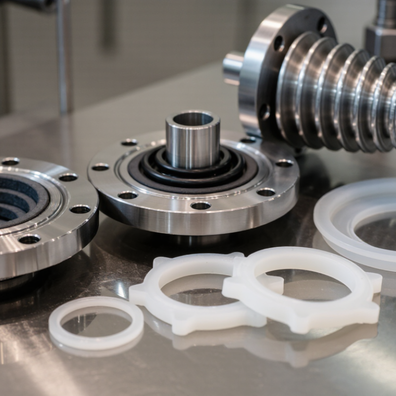
Valve seals control leakage around the stem, body, and seat. Each location faces a different failure risk.
The stem seal surrounds the moving stem and prevents process fluid from escaping through the bonnet. Packing is common, while bellows seals suit toxic, costly, or ultra-clean media.
The body seal closes the joint between valve sections. It usually uses a gasket or metal-to-metal interface.
The seat seal controls flow when the valve closes. Soft seats provide tight shutoff, while metal seats tolerate heat, abrasion, and harsh particles.
The U.S. EPA’s Protocol for Equipment Leak Emission Estimates identifies valves as a major source of fugitive emissions, sometimes contributing about 60% in process equipment inventories. That figure depends on plant design and inspection quality. API 622 and API 624 qualification methods also evaluate packing performance under cycling, temperature, and emissions testing. These standards remind engineers that a seal is not merely a spare part. It is a working system exposed to movement, pressure, heat, and chemical attack. In field service, a perfect material choice can still fail after poor installation. That deserves more attention.
Tips: Match the seal material with temperature, pressure, and fluid chemistry. Check stem movement before tightening packing. Excessive compression can increase friction and accelerate wear. Inspect body joints after thermal cycling. For seat leakage, use the applicable ISO 5208 or API 598 test class, then record the actual result rather than relying on assumptions.
Valve seals prevent fluid from escaping around moving or joined components. Their design depends on location, motion, and sealing mechanism. A small mismatch can cause leakage, wear, or difficult valve operation.
By location, common types include stem seals, seat seals, and body or bonnet seals. Stem seals close the clearance around a rising, sliding, or rotating stem. Seat seals control flow when the valve closes. Body seals protect the joint between major valve sections.
By motion, seals may be static, reciprocating, or rotary. Static seals remain compressed between fixed surfaces. Reciprocating seals handle repeated linear movement. Rotary seals manage turning shafts and changing contact pressure.
By mechanism, designers may use compression seals, lip seals, packing, or bellows. Compression seals rely on controlled pressure. Lip seals use a flexible edge. Packing fills a narrow clearance. Bellows reduce stem leakage but require careful fatigue assessment.
Tips: Match the seal with pressure, temperature, fluid, and movement. Inspect the stem surface for scratches. Check compression during maintenance. A seal that works well in one valve may fail elsewhere. Classification helps, but it is not perfect; actual service conditions can change the result.
A valve seal is the barrier that prevents fluid from escaping around a valve stem, plug, or connection. Its material affects leakage control, temperature resistance, chemical compatibility, and service life. A seal that works well with clean water may fail quickly in hot steam or abrasive slurry.
Graphite seals tolerate high temperatures and handle steam, hydrocarbons, and many industrial fluids. They are often formed as packing rings or flexible sheets. However, graphite can oxidize in certain high-temperature environments, so pressure and atmosphere require careful review.
PTFE offers very low friction and strong chemical resistance. It suits corrosive fluids and low-temperature applications, but excessive heat or mechanical loading may cause deformation. The details matter.
Elastomer seals, including rubber-like compounds, provide flexibility and reliable sealing under moderate temperatures. Their performance changes sharply with oil, solvents, ozone, and temperature. A swollen elastomer may appear secure while losing its recovery force. Metal seals serve demanding pressure and temperature conditions. Common designs use metal rings that deform against precisely machined surfaces. They resist harsh service, but installation requires clean surfaces and controlled compression. Small scratches can become leak paths. Seal selection should consider fluid composition, pressure cycles, stem movement, temperature changes, and maintenance access. A material chart is useful, yet real operating conditions often expose assumptions that looked reasonable on paper.
A valve seal prevents process media from escaping around the stem or body joint. Common types include elastomeric seals, bellows seals, and packing seals. Packing remains widely used because technicians can adjust or replace it without removing the entire valve. Its weakness is gradual wear. Heat, pressure, chemical exposure, and repeated stem movement can create a small but persistent leak.
API 622 evaluates packing performance through controlled thermal cycles, pressure exposure, and 1,510 stem movement cycles. This benchmark represents repeated operation, not a single factory inspection. The test also measures fugitive emissions during demanding conditions. According to the International Energy Agency’s Global Methane Tracker 2024, fossil fuel operations released about 120 million tonnes of methane in 2023. Small valve leaks matter within that larger picture. API 622 qualification helps compare packing designs using repeatable evidence, rather than relying only on appearance or installation claims.
Still, the 1,510-cycle result is not a guarantee of field life. Installation quality changes compression, friction, and leakage behavior. Real valves may face vibration, dirty service, temperature shocks, or long periods without movement. That is where specifications can become imperfect. Engineers should review test conditions, packing material, valve geometry, and maintenance records together. A qualified packing set is useful evidence, but site experience remains necessary. Small details decide performance.
A valve seal prevents process fluid from escaping around moving or joined parts. It also blocks dust, moisture, and outside air from entering the valve. In field inspections, I look for leakage traces, hardened material, and unusual stem resistance. These small signs often reveal seal failure before pressure drops become obvious.
Bellows seals use a flexible metal bellows to isolate the valve stem from the process fluid. They suit toxic, corrosive, or high-purity services because they can provide very low external leakage. However, repeated movement can cause metal fatigue. Diaphragm seals use a flexible membrane instead. They separate the actuator from the medium and work well in hygienic or corrosive systems. Their pressure and temperature limits need careful checking.
O-rings are compact elastomer rings fitted inside a groove. They are economical and effective for static joints, but incorrect compression, heat, or chemical exposure may cause swelling. Lip seals use a flexible sealing edge against a moving shaft or stem. They perform well in rotating or reciprocating applications, though friction and wear can increase over time. I have seen an O-ring selected correctly on paper but fail quickly because the groove was rough. That detail is easy to miss. Material compatibility, pressure direction, movement frequency, and maintenance access should guide the choice, not price alone.
This chart compares representative pressure capabilities for common sealing applications. Actual limits depend on seal material, temperature, size, fluid compatibility, installation, and operating conditions. Bellows seals are commonly used where low leakage and resistance to corrosive fluids are important; diaphragm seals suit isolation and control duties; O-rings support both static and dynamic sealing; and lip seals are mainly used for rotating shafts at relatively low pressure.
How can we help you?
Call to 0034 943884600 Contact usWe use cookies to ensure that we give you the best experience on our website. If you continue without changing your settings, we'll assume that you agree to receive cookies on the HINE website. For more information read our cookie policy page, click the link for more information.plugin cookies
ACEPTAR