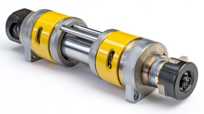

A hydraulic cylinder may look like a simple tube, rod, and pair of ports. In service, its performance depends on many smaller components working together under pressure. Buyers who understand hydraulic cylinder parts can ask better questions, compare quotations more accurately, and avoid mismatches that lead to leaks or premature wear.
The details matter. A piston seal must suit the fluid, temperature range, and operating pressure. A rod needs the right diameter, surface finish, and corrosion protection for its environment. Even a wiper matters. Dust, metal chips, or dried mud around a rod can damage sealing surfaces over time. Buyers should also check dimensions, materials, tolerances, and compatibility with the existing cylinder—not just the part name on a sales listing.
That sounds simple. It isn’t always. Product descriptions can be incomplete, and two parts that look alike may differ in fit or material. Requesting drawings, specifications, and clear photographs can help, but measurements should still be verified before ordering. When a cylinder supports critical equipment, consult its manufacturer or a qualified hydraulic technician rather than guessing. A low price may not represent good value if the replacement fails early. Still, not every costly option is better; the right choice depends on duty cycle, maintenance conditions, and available documentation. The following guide explains ten commonly purchased components, what each one does, and which details deserve a closer look before you buy.
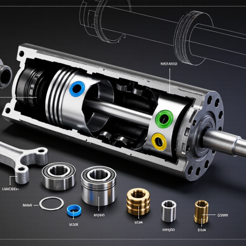
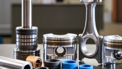
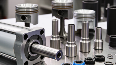
A hydraulic cylinder converts pressurized fluid into straight-line force. The barrel houses the piston and guides its movement. The piston separates the cylinder’s chambers, while its diameter helps determine force output. The piston rod transfers that force to the machine. Small parts matter.
Seals control fluid leakage between chambers and around the rod. A rod wiper helps keep dust and grit outside as the rod retracts. The gland supports and guides the rod, while the end caps close the barrel and connect the cylinder to its mounting points. Fluid ports direct oil into or out of the chambers; in a double-acting cylinder, each side can drive the piston. Some cylinders also use cushioning to reduce impact near the end of a stroke.
During inspection, look for oil around the rod, scratches on its surface, or damaged seal edges. A clean-looking rod is not proof that every part is sound. Even a small scratch can wear a seal, though the cause may be elsewhere. Replacement parts should match the cylinder’s dimensions, pressure rating, and operating conditions. Guessing from appearance alone can lead to poor fit or early wear.
The pressure housing contains hydraulic pressure and supports the cylinder’s working components. Its barrel forms the main tube around the piston, so bore diameter and surface finish matter. A rough or scored bore can wear seals and cause internal leakage. Wall thickness must suit the operating pressure, load, and mounting arrangement. Dimensions alone do not tell the whole story.
The head and cap close the barrel’s ends. The head commonly guides the rod and holds seals and a wiper; the cap may provide a mounting point or close the opposite end. Their alignment affects rod movement and seal life. Even a small misalignment can create uneven wear. It is easy to overlook.
Ports connect the cylinder to hydraulic lines, and their location affects hose routing and service access. Check the specified thread or connection type, port size, and flow direction before assembly. Keep port openings clean, since chips or grit can damage seals and control components. Inspect welds, threads, and sealing faces for visible damage, but do not treat a visual check as proof of pressure capacity. A drawing may look complete while leaving practical clearance unclear, so confirm fit against the actual installation.
A simplified double-acting cylinder typically has one barrel, one head, one cap, and two working ports. The barrel contains hydraulic pressure; the head and cap close its ends; and the ports provide connections for fluid flow. Actual configurations vary by cylinder design.
A hydraulic cylinder’s motion assembly turns fluid pressure into controlled force. The piston separates pressure chambers, while its seals limit internal bypass. Even small wear can cause drift, heat, or uneven movement. The piston rod carries that force outside the barrel, so surface finish and straightness matter. Scratches can damage the rod seal; a bent rod can load the guide unevenly. The rod end connects the assembly to the machine. It must transfer load without forcing the rod off-axis. A tight connection is not always a good connection.
Fluid cleanliness affects every moving surface. ISO 4406:2021 classifies hydraulic-fluid cleanliness using particle counts at ≥4, ≥6, and ≥14 μm(c). This gives maintenance teams a measurable reference when checking contamination risks. Still, a clean-fluid reading cannot reveal a misaligned rod end or worn piston seal. Inspection needs both fluid checks and close attention to movement, leakage, and scoring. The overlooked detail is often alignment.
Tips: Check the rod for dents and chrome damage before installation. Confirm the rod end moves freely through the machine’s full stroke. Look for side-loading marks near the guide. Record fluid cleanliness and seal condition together; the record may be imperfect, but it is more useful than guessing later.
The rod gland does more than hold a seal. It keeps the rod aligned and supports the sealing stack as pressure changes. The primary seal limits fluid loss; a secondary wiper removes dust and moisture on the return stroke. Wear rings guide the rod and piston, helping prevent metal-to-metal contact under side loads. Small parts. High consequences.
Fit and surface finish matter. A sharp rod edge can nick a new seal during installation, while a worn guide ring can let the rod tilt and load one side of the seal. ISO 5597 provides dimensional guidance for single-rod hydraulic cylinders, but a standard dimension alone cannot confirm compatibility. Buyers should check pressure, speed, temperature, fluid type, rod finish, and extrusion clearance against the cylinder maker’s design requirements. A drawing can look perfect; the real weakness may be a scratched rod.
Contamination deserves equal attention. ISO 4406:2021 classifies hydraulic-fluid cleanliness by particle counts; code 18 represents 1,300–2,500 particles per millilitre at 4 μm(c) and larger. That figure is a cleanliness code range, not a universal target for every cylinder. Follow the equipment specification and inspect the fluid when seals wear early. A practical buying check is to confirm seal material, gland dimensions, and wear-ring clearance together. Ordering each part separately can miss the fit between them.
| No. | Component | Typical location | Main function | Buyer checks |
|---|---|---|---|---|
| 1 | Rod gland (cylinder head) | At the rod end of the cylinder barrel | Houses the rod seal and guide; helps seal and support the rod as it moves. | Confirm bore and rod dimensions, mounting and retention style, material, and compatibility with the cylinder design. |
| 2 | Rod seal | Inside the rod gland, sealing against the reciprocating rod | Limits hydraulic fluid leakage from the cylinder along the rod. | Match the rod diameter, gland groove, pressure, fluid, temperature, and motion conditions. |
| 3 | Rod wiper (scraper) | Outermost position in the rod gland | Wipes dirt, moisture, and other contaminants from the rod as it retracts. | Check the rod size, wiper profile, exposure to contaminants, and fit in the gland groove. |
| 4 | Rod guide ring or bearing | In the rod gland around the rod | Guides the rod and helps carry side loads, reducing metal-to-metal contact. | Verify rod diameter, bearing width, clearance, material, and the expected side-load conditions. |
| 5 | Gland static seal | Between the gland and barrel or end cap | Prevents leakage at the stationary joint between cylinder components. | Confirm seal type, groove dimensions, fluid compatibility, temperature range, and joint design. |
| 6 | Buffer seal | Behind the primary rod seal, when included in the design | Helps manage pressure peaks and protects the primary rod seal in suitable seal arrangements. | Check whether the cylinder uses a buffer seal and confirm its profile, orientation, and compatibility with the primary seal. |
| 7 | Piston | Mounted on the piston rod inside the barrel | Separates the cylinder chambers and transfers hydraulic force to the rod. | Confirm bore and rod dimensions, seal and wear-ring grooves, attachment method, and surface condition. |
| 8 | Piston seal | In a piston groove, sealing against the barrel bore | Limits fluid bypass between the cylinder chambers during piston movement. | Match the bore, groove, pressure direction, fluid, temperature, and single- or double-acting arrangement. |
| 9 | Piston wear ring (guide ring) | Around the piston, running against the barrel bore | Centers the piston and carries side loads to help protect the piston and barrel surfaces. | Check bore size, ring width and thickness, clearance, material, and the number of rings specified by the design. |
| 10 | Anti-extrusion backup ring | Beside a seal in a rod or piston groove, where required | Supports the seal against extrusion into clearance gaps under pressure. | Verify groove dimensions, pressure conditions, clearance, material, and correct installation orientation. |
Note: Component profiles, materials, and operating limits vary by cylinder design, hydraulic fluid, pressure, temperature, and application. Confirm dimensions and service requirements before purchasing.
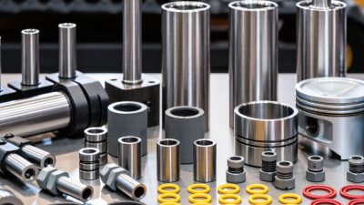
A cylinder barrel, piston rod, piston, seals, wear rings, and end caps each affect performance. Check the material against the working environment. A rod exposed to moisture may need corrosion-resistant protection, while seals must suit the hydraulic fluid and operating temperature. Small details matter. A seal that looks right can still swell or wear quickly if its compound is unsuitable.
Dimensions deserve more than a quick glance. Confirm bore, stroke, rod diameter, and mounting pin distances against the drawing or existing assembly. Measure thread type and port size too; similar-looking fittings may not connect properly. Check tolerances where parts slide or seal. A few millimeters can cause binding or leakage. I would not treat a matching nominal size as proof of fit.
Compatibility also depends on pressure rating, fluid type, temperature range, and mounting style. Compare these details across the cylinder and replacement parts, rather than checking each item alone. For example, a rod end may fit the pin but sit at the wrong angle under load. Ask for material specifications and dimensional records when they are available. Records can be incomplete, though, so verify critical measurements on the actual equipment before ordering.
How can we help you?
Call to 0034 943884600 Contact usWe use cookies to ensure that we give you the best experience on our website. If you continue without changing your settings, we'll assume that you agree to receive cookies on the HINE website. For more information read our cookie policy page, click the link for more information.plugin cookies
ACEPTAR